Omron NB HMI Training Course (NB-Designer)
Learn how you can use NB-Designer to Design and use NB in your systems

What you will learn
How create project in NB-Designer
How using any parts in NB-Designer
Upload and Download
Connecting NB to PLC
Why take this course?
Lecture 1: Create Project (Serial)
Lecture 2: Create project (Ethernet)
Lecture 3: Upload / Download
Lecture 4: Offline and Indirect Simulation
Lecture 5: Task Bar
NB-Designer provides a simple method (i.e. the Task Bar) to make the screen pop up or be minimized, to change the display of the screen and fast switch the screen display etc. Task Bar has 2 operation buttons, one of which is used to control the Menu Screen, and the other is used to control the Task Bar. You can set the Properties such as the Task Bar, whether to use the Menu Screen, color and position and so on in the [PT Property] in the Configuration and Setup Window. (By default, all the options in the Display Task Bar are checked.)
Lecture 6: Sheet
Common Sheet will always be displayed in the screen, and the components to be displayed forever can be put in Common Sheet. In this way, you can see the state of this component or operate this component at any time. The default Common Sheet is Frame 1. You can use [Change Common Sheet] function key to switch the other screen as the current Common Sheet, but only one screen can be used as the current Common Sheet.
Lecture 7: VNC
Lecture 8: Indirect Refrence
Lecture 9: System Information Message
Lecture 10: Bit Button & Bit Lamp
Bit Button component defines one touching area. When this area is activated, the bit address inside the PT or in the PLC can be switched to “On” or “Off” forcefully.
Lecture 11: Bit Switch
Bit Switch is the combination of the Bit Lamp and the Bit Button component. It defines a touching area, and the bit address inside the PT or of the PLC can be switched between On and Off state when this area is enabled.
Lecture 12: Command Button
Command Button component also defines a touching area and the state value will be input into the specified word address when the area is enabled.
Lecture 13: Word Lamp
Word Lamp is the component which will switch the display information according to the value of the specified word address.
Lecture 14: Word Switch
Word Switch is the component which changes the status value of the value specified for each status value and send the value to the specified address. The status value is changed by increasing or decreasing for each touch operation or by selecting from the list. When changing the status, the mapping value specified for each status will be sent to the specified memory. The statuses can be set up to 256.
Lecture 15: XY Graph
XY Graph reflects the correlation of two variables visually. If you want to monitor the XY Graph reflecting the changes of address values, the NB Unit can clearly displayed it out only by using this component.
Lecture 16: Animation
The Animation component is used to put the component into the position with the specified track in the PT, and this position is determined by the preset path and the data of PLC. The status and absolute position of the component in the PT is determined by the data in the 2 consecutive PLC memories. Generally speaking, the Read Address and the Read Address + 1 are used to store the state and the position in the preset path respectively. When the values in the position memory of PLC (Read Address + 1) change, the Vector Graphics or bitmap will jump to the next position in the preset path.
Lecture 17: Number Input / Number Display
The Number Input component can be used to display the current data contained in word address inside a specified PT or of PLC, to input data through the pop-up keyboard and to change the data contained in this address by pressing “ENTER” button.The Number Display component is used to display the data in the specified word memory.
Lecture 18: Text Input / Text Display
Text Input component can modify or display the data in the specified word memory, which is analyzed through the standard ASCII character table as default settings. The input data is saved to a consecutive memory with the “Registered Address” as the first address. Low-byte character codes are displayed on the left, while high-byte character codes are displayed on the right. The Text Display component can display data in the specified word memory, which is analyzed through the standard ASCII character table in default settings. Low-byte character codes are displayed on the left, while high-byte character codes are displayed on the right.
Lecture 19: Level Meter
The value specified of the communication address is displayed in level picture based on the upper limit value and the lower limit value set by [Level Meter Property].
Lecture 20: Analog Meter
Analog Meter can display the data in the specified memory by means of a Analog Meter diagram.
Lecture 21: Direct Screen
Direct Screen can make a specified screen pop up onto the current screen. The pop-up screen will be displayed within the area of the [Direct Screen]. Normally, the Direct Screen size should be set to same as that of the pop-up screen. There is no absolute limitation on the number of Direct Screen. However, a maximum of 16 Direct Screens can be displayed simultaneously during operation. The closing or opening of the Direct Screen is only determined by the bit address of the [Read Address] that control it, while Function Key can’t be used to close it. When this bit address is ON, the screen will pop up, and when it is OFF, the screen will be closed.
Lecture 22: Alarm / Alarm Display / Alarm Setting
The Alarm component will display all the alarm information enabled in the set area. The content it displays is the same as that displayed by the Alarm Display, and both of them are about the alarm information of a certain node switch (bit address). When the bit address which worked as alarm trigger is released, the alarm display will be removed. The alarm information displayed by the alarm is necessarily registered by “Alarm Setting”. When multiple alarms occur, the alarms will be displayed in the order descending to the newer (the top is the oldest and the bottom is the newest).
Alarm Display icon can be used to display the triggered preset alarm information by using the Neon Lamp in the area where the Alarm Display locates. The alarm information must be related to node address of a certain bit, and it will scroll from the right to the left when the bit address is triggered to the alarm state. The alarm information will continue to scroll until this bit address is switched to the nonalarm state. The alarm information must be logged in the [Alarm Setting] database in advance. (This component only displays the alarm information, and the component to be displayed must be logged in the [Alarm Setting] database).
Lecture 23: Data Log
The Data Log component acquires some PLC data and displays it in the manner of a Data Log at regular intervals. When each sampling period comes to an end, new data will be read from the PLC and displayed on the right of the Data Log, which ensures the real-time display.
Lecture 24: Recipe
The component of the Recipe transmits the data with consecutive memories. And the data can be downloaded from the recipe memory to the PLC or uploaded from the PLC to the recipe memory. The size of the data to be transferred can be set. For the NB Unit, the recipe memory with 128K word can be selected for recipe data storage.
Lecture 25: Scroll Bar
Scroll Bar is used to change the value in the specified word memory by pressing the slider.
Lecture 26: Event / Event Display / Event Setting
Event component is used to display the event information registered in “Event Setting” and whose current state satisfying the triggering conditions. The Event component will display triggered event information one by one according to the time sequence of the triggered event. If the accurate time needs to be displayed, the RTC must be used or the Time must be read from the PLC. If multiple events are triggered, the events will be displayed in the order of descending or the latest event will be at the top and the oldest event at the bottom. In addition, if 1024 events or more are triggered, the event will be deleted in order from the oldest event. When only a particular event is displayed, there may be the cases where the event suddenly disappears because of the hidden events of which the number has significantly increased to exceed 1024.
Lecture 27: Word Neon Lamp
The text string which is specified as Label is displayed in loopy-moving way, and it supports the label contents corresponding to 256 (max.) states in the loopy-moving way.
Lecture 28: Bit Neon Lamp
The text string which is specified as Label displayed in loopy-moving way, and it supports the label contents corresponding to State 0 and State 1 in the loopy-moving way. The difference of the Word Neon Lamp and the Bit Neon Lamp is the controlling method, and the former selects the different states ranging from 1 to 256 by changing the memory value, while the latter changes the display state (only 2 states available) by changing the state of the control bit.
Lecture 29: Touch Trigger
The Touch Trigger component is applicable to the conditions where the several components can be triggered to act not through the triggering method. When the triggering conditions for the specified memory of the Touch Trigger component are satisfied, the components placed in the valid area for the Touch Trigger component can be triggered to act.
Lecture 30: Table
The Table component can make the selection type of “Select by row”, “Select by Column” and “Select by cell”. The user can set the “Row”, “Column”, “Color when Selected”, “Background Color”, “Border Color”, and write the selected Row No. and Column No. into the specified memory.
Lecture 31: Data History
The Data History component can be used to read a series of date in consecutive memories from the specified word memory(s) inside PT, PLC or word memory(s) of the controller periodically and display them in the table form.
Lecture 32: Operation Log
The Operation Log component can be used to record or display the operations made by the users to the PT in the table form. The operation log will be stored into the external memory in CSV format.
Lecture 33: Scale
It is applicable to the conditions with the requirement of equal-division notation.
Lecture 34: Timer
Timer is a kind of component performing the timing. When the timing is over, it will play the other corresponding functions such as periodical Macro instruction execution, parameter setting and data transmission etc.
Lecture 35: Bitmap
Bitmap component is used to call and display the bg-form graphics registered in the system graphics library or the graphics library in Project File Window. Bitmap component is not controlled by the memory, and doesn’t have multiple states, thus the bitmap corresponding to the graphics state specified by you at the designing time will always be displayed.
Lecture 36: Vector Graphics
Vector Graphics component is used to call and display the vg-form graphics registered in the system graphics library or the graphics library in Project File Window. The Vector Graphics component is not controlled by the memory, and doesn’t have multiple states, thus the Vector Graphics corresponding to the graphics state specified by you at the designing time will always be displayed.
Lecture 37: Data Transmission
Data Transmission component can make the data in the specified memory address transferred to the other memory address. Data Transmission can be triggered by the manual touching method or the state change of the specified address.
Lecture 38: Date/Time
The Date/Time component can display the value of the internal RTC clock of the PT in the set format.
Lecture 39: Indirect Shape
The Indirect Shape component can modify the positions and sizes of the rectangle, ellipse or line by changing the value of the memory.
Lecture 40: Multifunction
The component which is unified the Bit Button and the Word Switch can operate the both the bit set and the word set through one key. The Multifunction component can be created by using the mouse to click [Components] - [Button/Switch] - [Multifunction] or dragging [Multifunction] component from [Project Library Window] - [Function Parts] to the Edit Window. The number of Actions which can be set by the Multifunction is 16 at max
Lecture 41: Text Library and Multi Language
Text Library can be used to store the text contents needed by the project, thus preventing the label with the same text from being input frequently. In addition, Text Library can be used to the conditions with the requirement of multi-language support to realize the switching among the multiple languages for the PT Edit screen. NB-Designer currently supports up to 32 kinds of languages setting.
Lecture 42: Variable Table
Variable Table is a useful address logon library, which prevents the inconvenience resulting from repeated input of address, thus saving a lot of time. Check the [Use Variable] check box in setting items for each component to use the address which was registered to the Variable Table with the settings for each component.
Lecture 43: Security
can be set for each level at the request of the users, and the greater the level number, the higher the level. 15-level is the highest and 0-level is the lowest. When the security level is 0, it means no password. 0 can’t be used for setting the password.
Lecture 44: User Permission and User Information
The software opens 32 users and 32 operation permissions for free use. The users and operation permission can be set separately, and the operation permission is not limited to the users. And the online user addition/deletion and permission modification can be done in the PT.
When the system uses User Permission function, the related information of the current login user can be displayed in the table form by using the User Information component. The User Information component must be used in combination with the User Permission, otherwise it will not work.
Charts
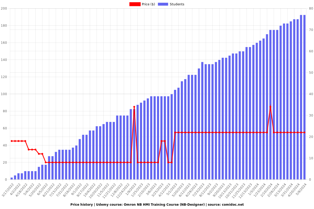
Price
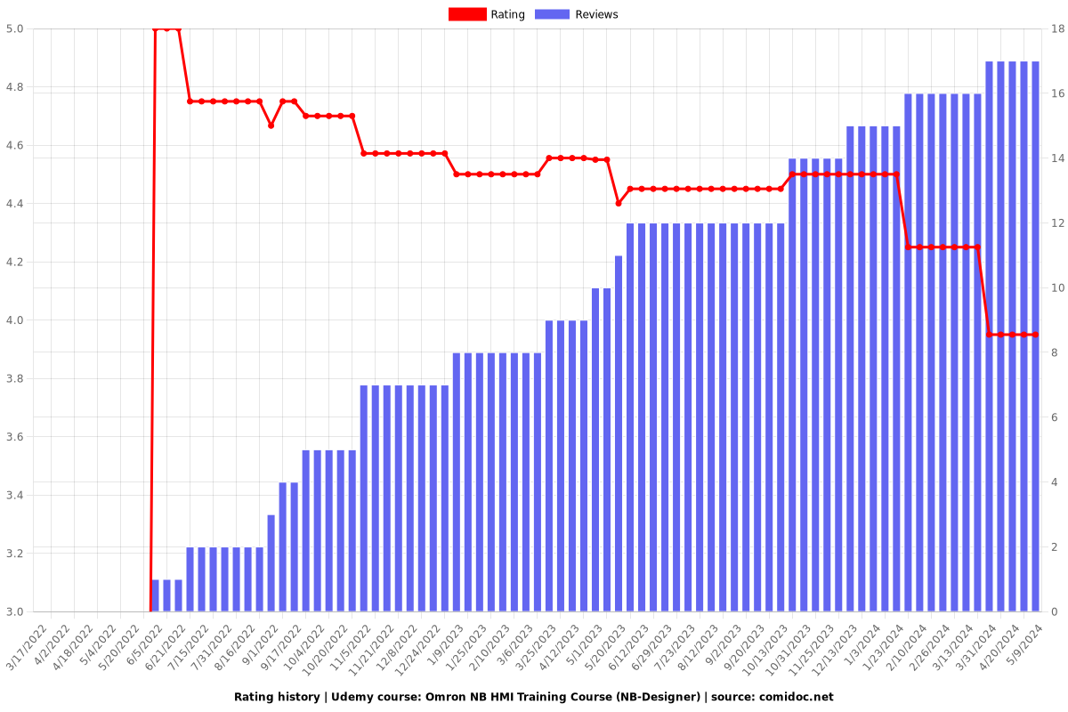
Rating
Enrollment distribution