4.55 (11 reviews)
☑ Provide evidence that the certified user has displayed the CAD skills to confidently use Solid Edge. • Once users pass the certification test, they are presented with a certificate of accomplishment, signed by SIEMENS PLM Solutions, and the right to use the Solid Edge Certified Professional logo. • Add Solid Edge 3D modeling as a skillset to your resume.
STAND OUT WITH SOLID EDGE CERTIFICATION - UPDATED JAN 2021
Even if you presently know nothing about 3D Design and Siemens Solid Edge this course is geared to accelerate you professional development and validate your skills by preparing you to pass the Solid Edge Level 1 certification exam with confidence. The class and the Siemens Solid Edge software are free to all students.
This course is not a shortcut to certification. To pass you will need to cover all the course material and spend time using and experimenting with Solid Edge and get industry recognized credentials.
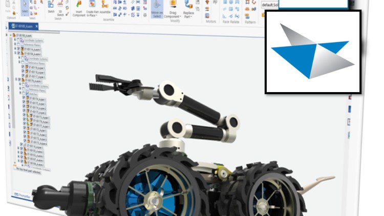
Solid Edge with Synchronous Technology is a computer-aided design (CAD) system for mechanical assembly, part modeling, drawing production, and simulation. Solid Edge boosts essential CAD user productivity by capturing engineers' solid modeling design intentions through inference logic and decision-management concepts. Synchronous technology makes it possible to modify the design of any model, without having to know how it was constructed.
Part 2 of Solid Edge Training & Certification
053 Draft Angle
054 Creating Patterns
055 Fill Pattern Options
056 Pattern Along Curve
057 Detach Feature and Re-add Later
058 Lofted Protrusion
059 Loft Command - Understanding Live Loft Adjustments
060 Creating a Table with the Loft Command
061 Lofted Bowl
062 Lip Command
063 Swept Protrusion
064 Core and Cavity - Creating a Simple Mold
065 Dimension Formulas
066 Assemblies
067 Opening a Part from an Assembly
068 Assembly Constraints - Mate & Align
069 Adding Parts to an Assembly
070 Adding Motion to an Assembly
071 Ground Relationship & How to Delete
072 Insert Relationship - Assembly Constraints
073 Align Option - Floating
074 Assembly Explode
075 Building Assemblies
076 Assembly Center-plane Relationship
077 Creating Assembly Motion
078 Assemblies & Physical Motion
079 Maintaining Parallel Motion with an Assembly
080 Assembly Connect Constraint
081 Create in Place Assembly Command
082 Dynamic Clipping
083 Assembly Section Cuts
084 Detailing - Placing Parts on a Detail Sheet
085 Drawing Standards
086 Placing Drawing Views
087 View Updates & Shading Options
088 Assembly Detailing - Placing an Exploded View on a Drawing Sheet
089 Assembly Parts List
090 Magic Wheel - Understanding How to Manipulate Parts
091 Bulk Rotate with the Magic Wheel
092 Working with Different File Formats - IGES - Parasolid - STEP
093 Creating a Tool-cutter with the Magic Wheel
094 Design Intent - Relationship Recognition Functionality
095 Design Intent - Recognizing Relationships
096 Face Relate - Design Intent
097 Tangent Face Relate - Design Intent
098 Parallel Face Relate - Design Intent
099 2D Data - Opening DXF and DWG Files in Solid Edge
100 2D Data - Working with AutoCad 2D Data
101 AutoCad 2D to SolidEdge 3D
Practice Tests
102 Practice Test - Part 1
103 Practice Test - Part 2