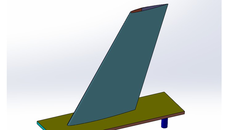
CFD analysis of ONERA M6 wing - Part 1 Geometry modeling

CAD modeling of ONERA M6 wing in Solidworks and domain creation in Spaceclaim that will be used for subsequent CFD Study

4.00 (5 reviews)
Udemy
platform
English
language
Other
category
instructor
120
students
2 hours
content
Oct 2022
last update
$44.99
regular price

What you will learn

Understanding of test case and getting important data about ONERA M6 wing such as airfoil coordinates, 3D details etc.

Creating accurate CAD model using Solidworks as per specifications given in AGARD report

Creating full model and domain in Spacleclaim ready for meshing in ICEMCFD

Creating named selections/boundary conditions for different parts

Description

ONERA M6 is a classical  test case for CFD validation. Although geometry is simple, but the flow field involves complex flow features such as  transonic flow (Mach No. 0.7 - 0.92) with shocks, boundary layer separation etc. The ONERA M6 wing was designed in 1972 by the ONERA Aerodynamics Department as an experimental geometry for studying three-dimensional, high Reynolds number flows. ONERA is a swept back wing, with half span. It is external third of M5 Wing without twist.


In this three part course series, you will learn about the conducting CFD analysis of ONERA M6 wing as per data given by  AGARD AR 138 1979 by Schmitt, V. and F. Charpin.


Part 1 (Present course) deals with geometry modeling in solidworks and domain creation in spacelaim according to above reference. Part 2 will teach to create high quality hexa meshing for the same wing in ICEMCFD. With consideration to resolve boundary layer and shock wave. Third part will teach you about conducting high quality CFD analysis in Fluent and post processing of data such as lift and drag coefficient. And also coefficient of pressure at various span locations.

Learning outcomes of this course:
1. At the end of this three part course/tutorial, student will be able to perform CFD simulation of exteneral, viscous, compressible flow around 3D geometry at transonic conditions using various turbulence models and appropriate Y+ values.

2. Student will be able to understand/learn all processes involved in high fidelity CFD analysis such as geometry creation, meshing, CFD setup, solution and post processing.

3. Student will be able to validate CFD results against experimental data from AGARD report.

4. Following things will be covered:

  • Geometry generation in Solidworks

  • Hemisphere domain in Spaceclaim

  • Hexa meshing in ICEMCFD

  • Mesh import, boundary conditions specification, material properties, solver settings, report definitions, hybrid initialization etc.

  • Steady state, 3D Reynolds-Averaged Navier-Stokes

  • Spalart-Allmaras, K-Epislon, Shear Stress Transport SST and transition turbulence models

  • 2nd order upwind flow scheme

  • Compressible, implicit solver

  • No slips wall, Symmetry and pressure Far-Field boundary conditions

  • Convergence acceleration using latest options in Fluent 2022 R1

  • Parallel solver

  • Post processing of results

  • Validations of results against experimental data.

  • solution convergence assessment based on lift and drag coefficients.


Resources:
You will get following resources in this course 

1. All power point slides

2. AGARD Report

3. All files including geometry, domain, hexa mesh, solved case and data files, excel file for data, aerofoil coordinates and also geometry from NASA.


Problem Setup

This problem will solve the flow past the wing with these conditions:


  • Freestream Temperature = 288.15 K

  • Freestream Mach number = 0.8395

  • Angle of attack (AOA) = 3.06 deg

  • Reynolds number = 11.72E6

  • Mean aerodynamics chord = 0.64607 m


These transonic flow conditions will cause the typical “lambda” shock along the upper surface of the lifting wing.


Content

Introduction

Course introduction
Problem description
Downloading important files and data
Files available in this course

CAD Modeling in Solidworks

Launching Solidworks and importing airfoil coordinates
Creating main blade
Creating initial tip region using revolve
Modifying tip region to get shape similar to file available from AGARD
Comparing CAD model from this course and downloaded from NASA

Creating hemispherical domain around ONERA M6 model

Importing CAD model and creating full model in Spaceclaim
Correcting trailing edge in spacelcaim
Creating hemispherical domain around ONERA M6 Model
Defining named selections

Screenshots

CFD analysis of ONERA M6 wing - Part 1 Geometry modeling - Screenshot_01CFD analysis of ONERA M6 wing - Part 1 Geometry modeling - Screenshot_02CFD analysis of ONERA M6 wing - Part 1 Geometry modeling - Screenshot_03CFD analysis of ONERA M6 wing - Part 1 Geometry modeling - Screenshot_04

Reviews

BERKAY
February 18, 2019
Dade basit bir anlatım var. Ancak eğitim cok temel seviyede . Daha fazla örnek olsa daha iyi olurdu. Başlangıç için gayet iyi .
Muhammad
August 12, 2018
As a CFD researcher i have found this course very comprehensive, knowledgeable and productive. After completing this course, the expertly level of any FEA and CFD engineer will definitely improve. Keep it up.

Charts

Price

CFD analysis of ONERA M6 wing - Part 1 Geometry modeling - Price chart

Rating

CFD analysis of ONERA M6 wing - Part 1 Geometry modeling - Ratings chart

Enrollment distribution

CFD analysis of ONERA M6 wing - Part 1 Geometry modeling - Distribution chart
4901724
udemy ID
9/27/2022
course created date
10/27/2022
course indexed date
Bot
course submited by